wanted to simplify the PCV (positive crankcase ventilation) system on my car. The stock setup works well, but over time the materials used to produce these specially formed pipes breaks down gradually due to oily vapour, heat, manhandling when replacing adjacent parts.. etc etc
So I'm doing this for a variety of reasons:
No oily vapour should re-enter the intake. It'll be caught in the catch can. This should:
Keep boost pipes free from recirculated oil vapour
Octane of the fuel shouldn't be reduced (oil vapour reduces octane apparently)
No need to clean throttle body again
No boost leaks from the stock VW pipework under the manifold. Remember, anything in the inlet is either boost or vacuum. If a vac pipe connected to the manifold has a split, it'll leak both under vacuum and boost conditions and the ECU will need to compensate. If enough compensation has to occur that the ECU thinks it's out of tolerance, you'll see a CEL on the dash
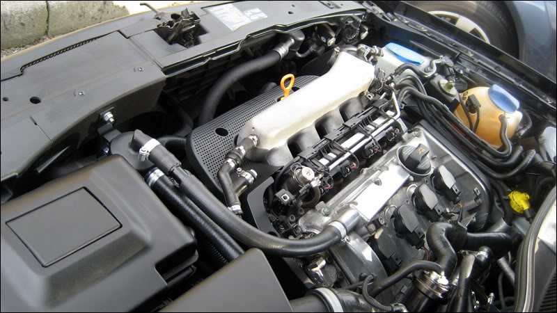
The first thing I did was to remove both engine covers. Under the lower cover I loosened the metal plate which houses the N112, the N249, a checkvalve and a small maze of vac pipes
2 x 10mm bolts holding the SAI (secondary air injection) pump inlet pipe
then 2 x hex bolts holding the plate to the manifold

Carefully lift the plate from out of the clip on the side of the dipstick holder. If your dipstick holder's never been replaced it'll be very fragile and it'd be a good idea to replace it now for what it costs (about £5-6)

Now I started removing all the stock pipework from the top
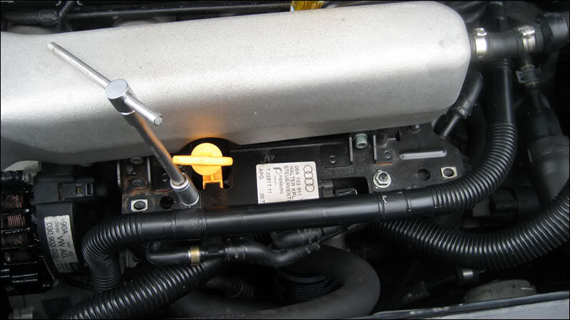
See right behind the dipstick, there's the first small L section of pipe that leads to the suction jet pump Y piece. This is the pipe in which I've previously inserted a checkvalve, to stop boost before it hits the suction pump

I removed that, leaving the suction pump end exposed

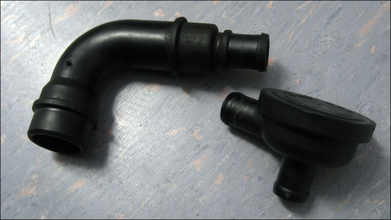
Next was the infamous for splitting upper breather, on the passenger side of the rocker cover
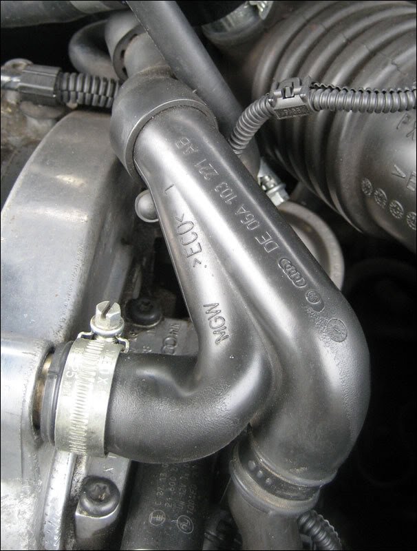
It attaches to the TIP via the 'hockey puck' accumulator valve
Removed
Then I disconnected the brake booster line, leading from the suction pump

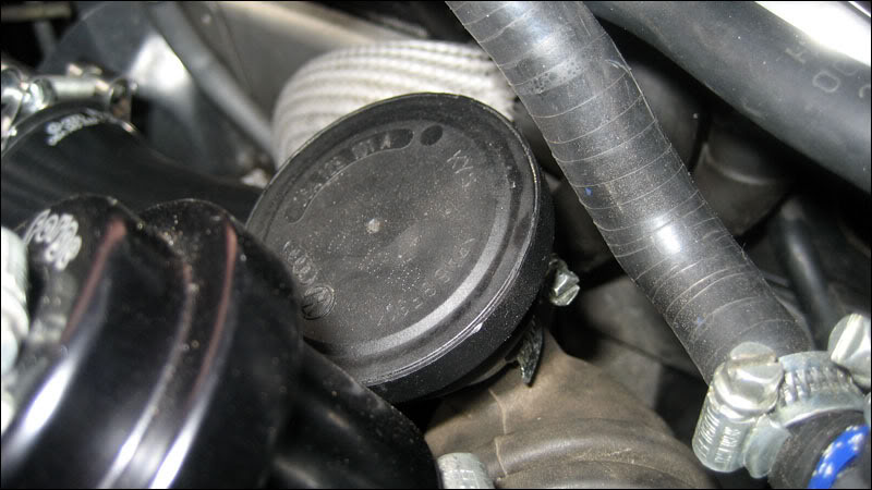
and finally I took out the lower breather pipe which is located right on the oil filter housing
You can see it on this picture from above, but unfortunately it's not in focus
I used a long shafted flathead screwdriver to prise off the C clip that holds it in position
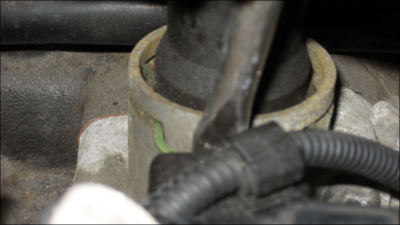
There's an O ring in there too, careful not to lose it!
Removed

Now I managed to shimmy all the pipework clear and took this photo. The Upper breather Y pipe and the L piece leading to under the manifold are not attached, as mentioned above, I disconnected before removal

Yeggers! Look at that sludge that's accumulated

Stuff like this clogs the PCV valve, the suction pump and will make it into your TIP..


Keep these 2 parts for the new installation
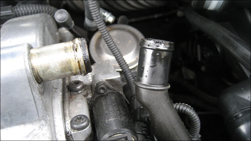
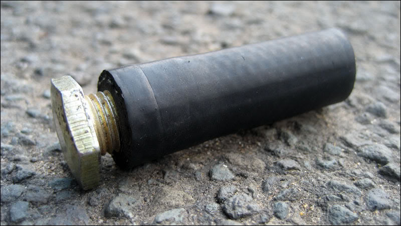
Now I want to cap the vacuum source under the manifold. It's not going to be used, all the pressure is positive coming from the crankcase and upper breather anyway and it'll be caught in the can. The fumes will also pull via the TIP connection when under acceleration. I used a small length of 3/8" ID pipe with a bolt screwed tightly into it
I'm also wanting to cap the brake booster line and just use the 1 vac source for brakes. It works on the AGU and ARZ so no reason it shouldn't work on an AUM right? I used a 1/2" piece of nylon rod and a jubilee clip but have since replaced this section of the brake booster line. Picture of revised piece to be edited in later

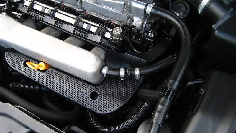
New picture to show the new brake booster line. I retained the original check valve as you can see, and it now looks a lot neater
All that's left to do now is cut new 3/4" or 19mm ID pipes, and connect the catch can between both breathers and the TIP
upper breather---catch can---TIP
lower breather /
The can
Saikoimichi Type 951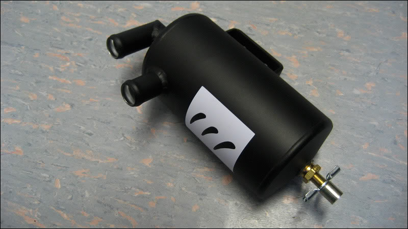
The hose I got from
Hosequip - I spoke to Josh who really is the most helpful fella in the universe. He sorted out some oil pipe so it shouldn't break down over time with all the vapours. As mentioned it's 3/4" or 19mm inner diameter stuff and I used around 1.5 metres
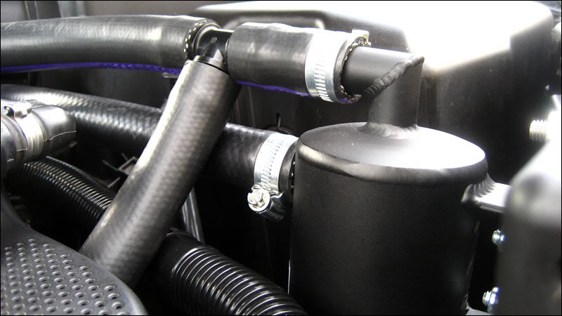
I connected the upper and lower connections to a T piece, and led this into the inlet of the can (top port)
I then connected the outlet (bottom port) of the can back to the hockey puck valve on the TIP

What I've done here is replace a system that I'm beginning to realise is slightly different depending on the model year of your car
AGU's and ARZ's seem to have only the one hose from under the manifold, straight down to the PCV valve
AUM's like mine (late 2000, X reg) have the hose, split into a Y 'suction jet pump' VW call it, top half coming up through the inlet manifold and joining onto the brake booster line off the passenger side of the manifold. The bottom split goes to the PCV valve
AUM's are different on the later models, my friend Lee has a Y reg that is different. Ste2 has a 53 reg that's also like this and so does Calimori.
They, like the AGU have the single pipe from inlet manifold to PCV, but an additional vac nipple right next to the PCV vac source, that also splits in the form of a suction pump, one half going to the TIP (presumably for pull under boost) and the other coming up through the manifold runners and into the brake booster line off the passenger side of the manifold
I'm not sure what an AUQ setup's like. I haven't seen one to pay any real attention to so if someone knows please post it here

So far I have emptied out a couple of table spoons worth of oily water, so it does appear to be working. I'm going to pull the inlet pipe off soon though just to check everything's flowing okay, with no sludgy buildup


 just an option to think about